

Fuel lines for MAN D2866 LE401
24 parts
Assembly diagrams in this category
- air intake
- coolant bleeder pipe
- cooling water lines
- crankcase
- distributor
- drip oil line
- exhaust elbow
- exhaust manifold water cooled
- fuel lines
- heat exchanger
- injection pump drive gear
- injection pump shut-off device components
- intercooler cooling water pipe
- intercooler elbow
- intercooler water space cover
- oil filter oil cooler
- oil measurement
- oil suction line
- pressure regulating valve
- Raw water pipes
- raw water pump drive
- raw water pump mounting
- surge tank
- turbocharger
- turbocharger charge-air pipe
- turbocharger cooling water lines
- turbocharger exhaust elbow
- turbocharger oil pressure pipe
Other subcategories of fuel system
Other categories of the D2866 LE401
About fuel lines for the MAN D2866 LE401
24 part numbers in this subcategory of fuel system for the MAN D2866 LE401. Quantities and fitment follow the manufacturer catalogue for this engine.
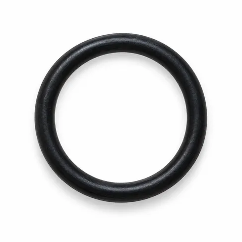
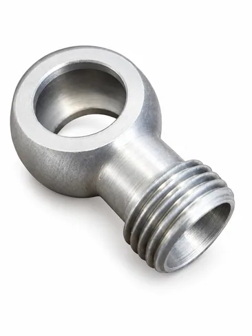
The broad drawing for low-pressure piping: single fuel lines and line assemblies, hose pipes, overflow valves, and the hollow screws, ring, twin ring and T-unions, clamps and brackets along the run. A line is bent for one route on one engine version, so the number on the old line is the safest reference.
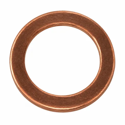
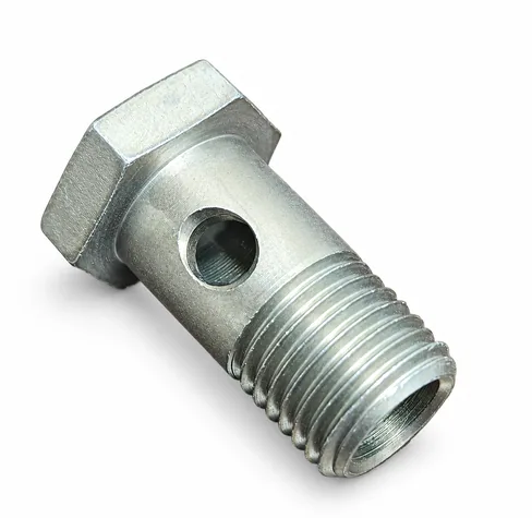
Hollow screws are listed in several lengths on the M14x1.5 thread, and the copper seals under them (A14X20-CU and others) are normally renewed whenever a joint is opened. The overflow valve (2.0–2.5 bar) looks much like a hollow screw but is a separate part. Narrower drawings such as Fuel lines supply and Fuel lines return exist for some engines.
Can’t find
the part?
We’ll find the best spare part options for you

